Effects of Wing Sweep In Subsonic Flow Regimes - RANS CFD Analysis
Overview and Objectives
The objective of this study is to determine the effects of wing sweep on a High AR, tapered trapezoidal wing. Aspect and Taper ratio were kept constant at 10 and 0.5 respectively in order to ensure that wing sweep was the only independent variable at play. The freestream was limited to incompressible and subsonic conditions.
- Reynolds Number: 1,000,000
- Models: k-⍵-SST
- Steady state solution: final time step
- Static pressure: P∞=101325 Pa = 1 atm
- Static temperature: T = 300 K
- Incompressible: Mach = 0.05
- Wing Airfoil: NACA 0010
- Primary Wing Dimensions: Characteristic Length = 2.66667 m, Characteristic Area = 20 m^2, Ar = 10, Taper Ratio = 0.5
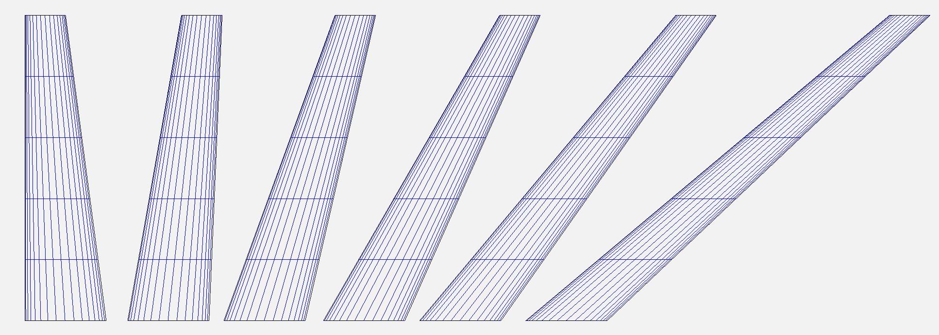
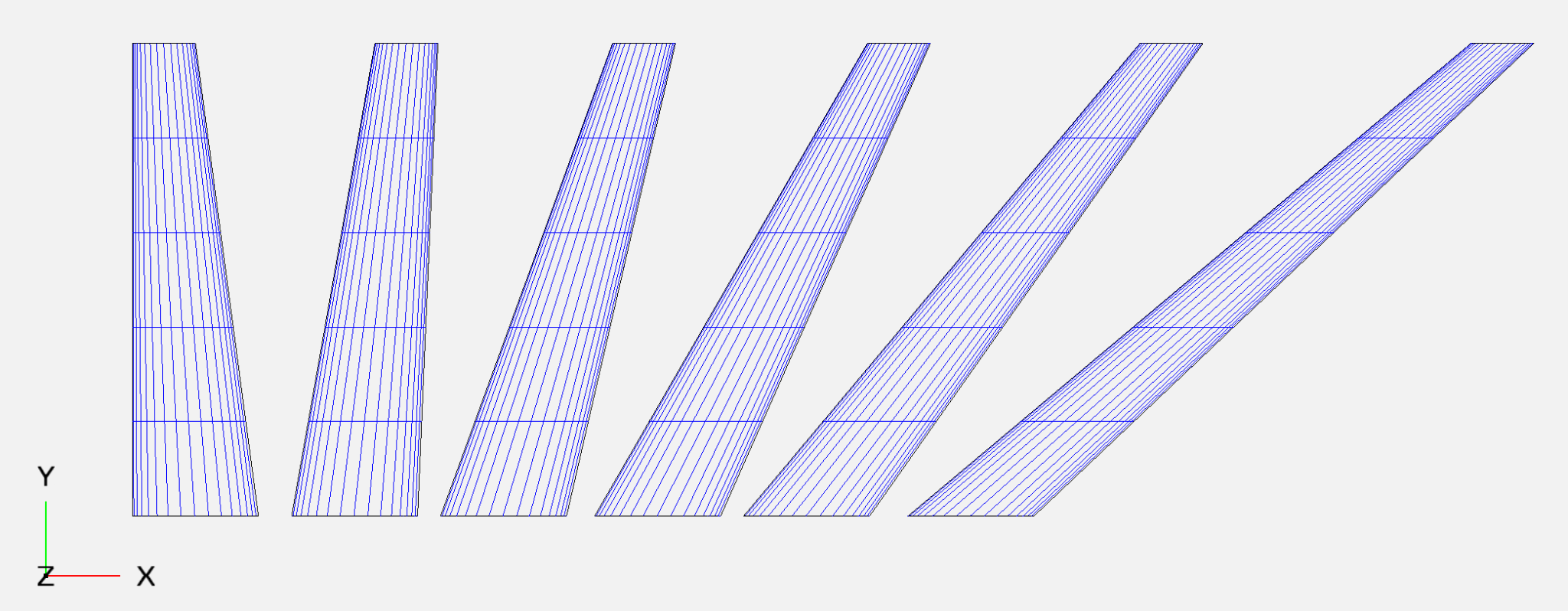
The variations in the wing Geometry can be seen in the list below:
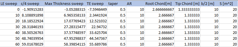
Table 1: Number of Cells for each Airfoil Case
A geometric illustration is also provided below:
Mesh Details
In order to simplify the meshing process and avoid spending days on meshing each of the unique geometries, a simplified meshing approach was utilized, which despite its inefficient use of cells was able to accurately characterize all the flow features, including the boundary layer and freestream.
Table 2: Number of Cells for each Airfoil Case
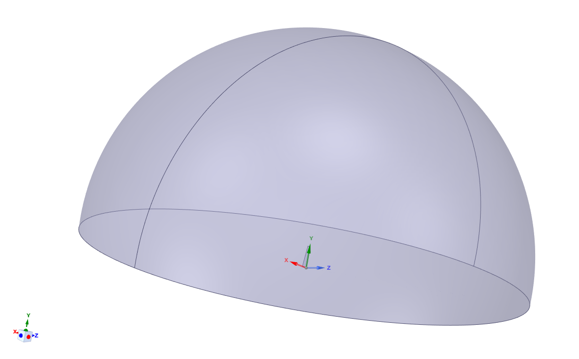
A half sphere enclosure was used in order to allow changing the angle of attack at the inlet by changing the velocity components in the x and z directions rather than geometrically realigning the wing with respect to the normal freestream flow.
The size of the enclosure is at least 10 span lengths away from the wing in any direction, which should be more than enough for an accurate characterization of freestream conditions similar to an actual flight. The bottom wall was modeled as a zero shear stress wall.
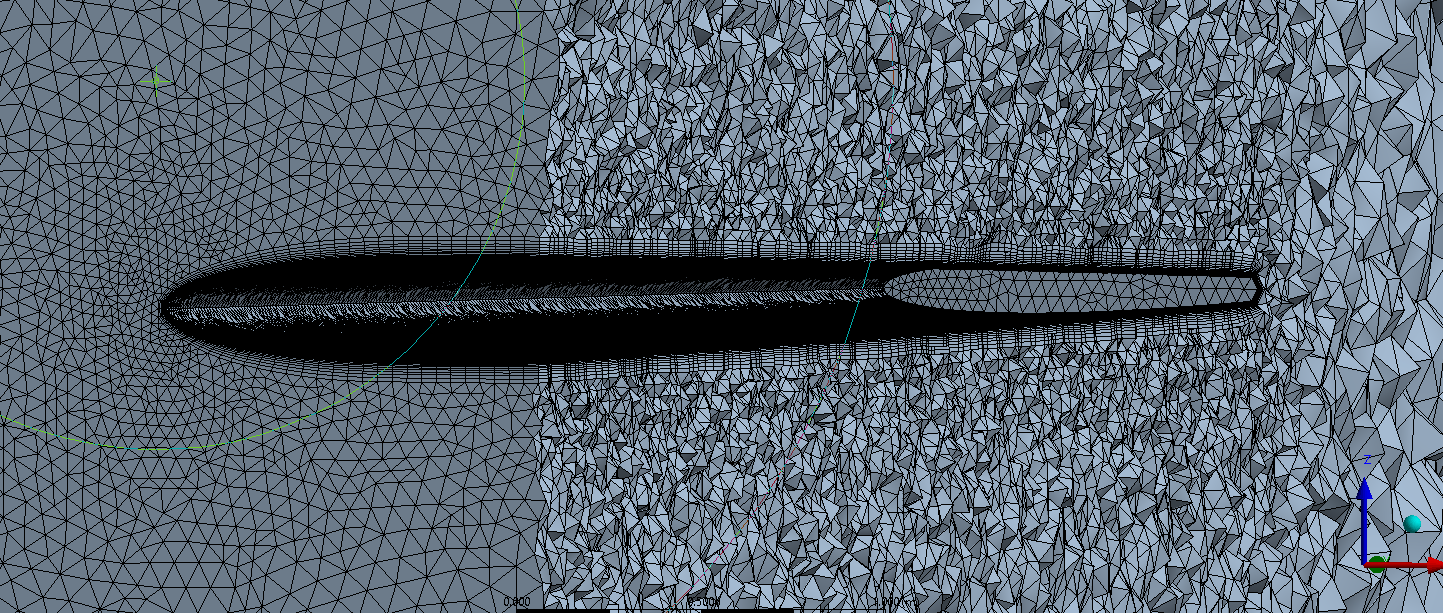
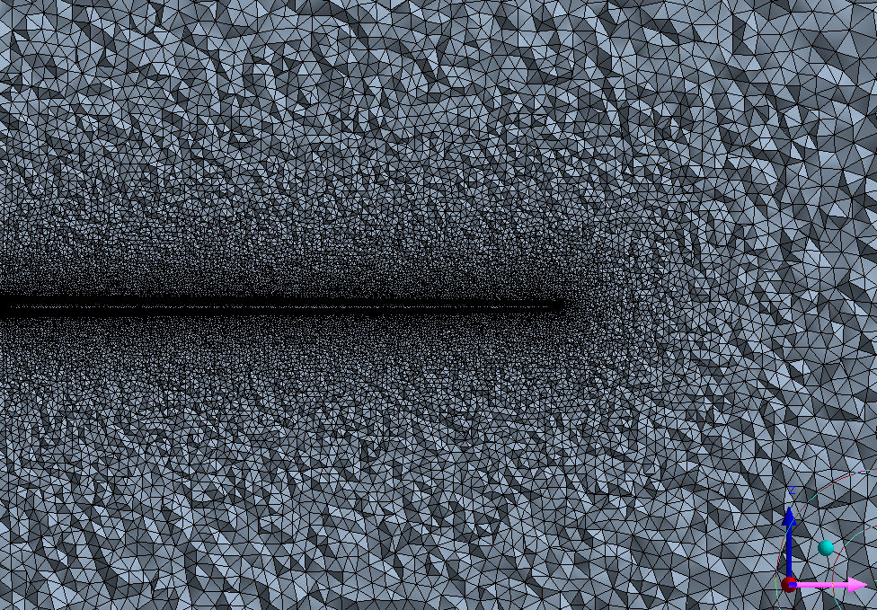
As can be seen in figures 3 and 4, excellent mesh densities were generated in order to properly characterize the flow. Any further refinement was not possible due to computational constraints of the author’s set up (mostly in terms of time since each wing iteration required 4 separate simulations for each angle of attack.)
Analysis: Aerodynamic Forces
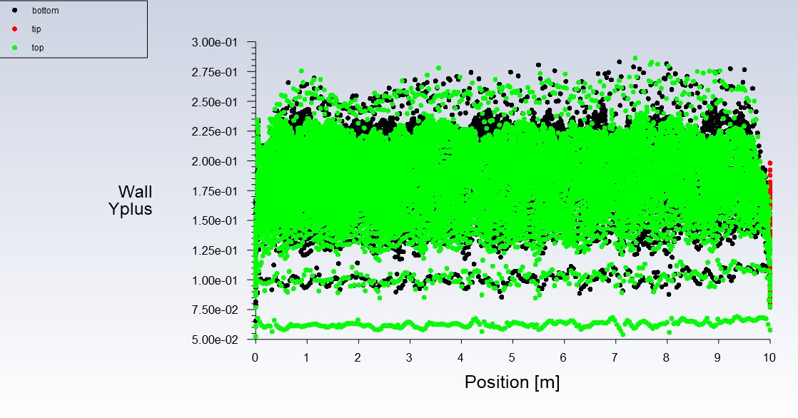
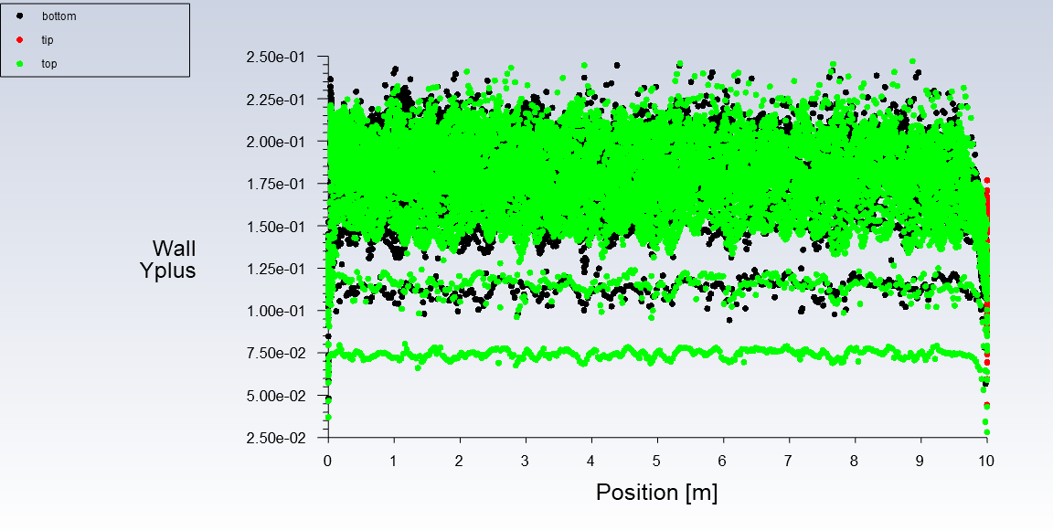
According to figures 6-7, it is evident that the boundary layer has been well meshed give that the y+ values are below 1.
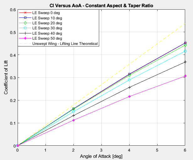
According to figure 8, increasing sweep lowers the lift slope of the wing, which corresponds well to theory. The yellow line, representing a thin lifting line model for a 10 aspect ratio wing, seems to be really close to the CFD results, which somewhat validates the simulation.
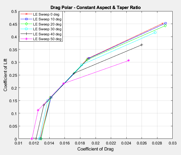
It also seems like increasing sweep decreases drag at lower angles of attack, where skin friction drag is dominant, while increasing drag substantially with higher angles of attack, where induced drag is much more dominant. The higher induced drag does make sense since increasing sweep tends to change the loading on the wing and decrease its oswald efficiency, however, the case of lower skin friction drag is somewhat unexpected since the total reference area was kept constant. Perhaps there is some variation in the wetted area of the wings. Lastly, it should be noted that at mild sweep angles, there is very little difference in drag and lift alike, which means that aligning hinge points and quarter chords on the wing or for some other structural reason by changing its sweep isn’t very detrimental aerodynamically.
Bending and twisting moments were normalized with respect to the characteristic length and area provided in the beginning of this report.
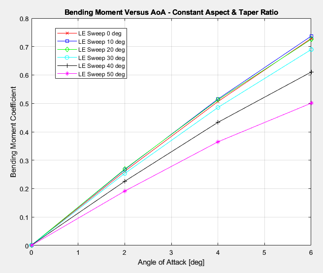
It isn’t surprising to see that wing bending moments decrease as sweep is increased because even geometrically, it is obvious that the center of pressure of the wing moves in closer to the wall (or fuselage on an aircraft), thereby decreasing the moment arm and subsequent bending moment.
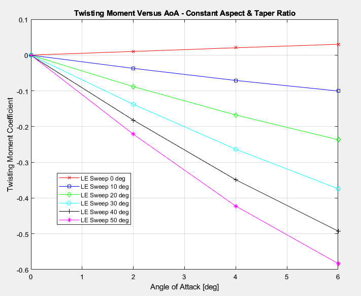
It is evident however that twisting moments increase substantially as wing sweep is increased. This will undoubtedly increase the trim drag on the aircraft and potentially lead to control issues if not addressed correctly.